![]()
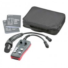
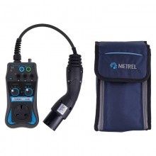
Includes: Continuity/earth bond lead Blow moulded caseEVA-T1 Type 2 to Type 1 connector adaptor.
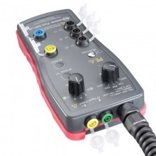
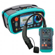
The Megger EVCC300 represents a new concept in electric vehicle charger checking, providing a simple, all in one solution. The name simply means: Electric Vehicle Charger Checker 300 = mode 3 chargers.
The compact, ergonomically designed instrument allows the user to quickly ensure a charger is in a safe, working condition. This could be done prior to putting back into use following maintenance, or simply as a regular health check to ensure everything is safe and working as it should be.
The EVCC300 is capable of checking both the safety and operation of a mode 2 and single-phase, mode 3 electric vehicle charger and does it in a simple, easy-to-use manner. One of the benefits of the EVCC300 is that it not only sets control pilot conditions to allow other electrical tests or to observe the charger’s reaction, it can also read the code received from the charger.
The control pilot signal (CP) is then compared with the requirements of IEC 61851-1:2017, without the need for a separate oscilloscope. This makes the EVCC300 a unique solution to ensuring EV charger safety and reliability.
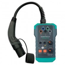
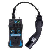
The EVCC300 can check the safety and operation of single phase mode 3 chargers with type 2 connections and type 1 connections using an adaptor supplied as standard.
APPLICATIONS
Safety and operation checks on mode 2 and single phase mode 3 charge points.
Connects to SAE J1772 Type 1 and Type 2 charger connectors only.
Checking charger following installation before hand over to customer.
Checking charger as part of a regular maintenance schedule.
Checking charger following repair before hand over to customer.
Checking chargers following manufacturing as part of a QA inspection.
Fault checking when customer reports charger issues to car dealership/service centre.
| EVSE Standard | IEC 61851-1:2017. |
| EVSE Supply Options (set in settings) | 1. 230 V single-phase. |
| 2. 120 V single-phase. | |
| 3. 208 V two-phase. | |
| 4. 240 V two-phase. | |
| Supply Measurement | |
| Voltage range | 5 V to 300 V. |
| Voltage resolution | 1 V. |
| Voltage accuracy | ± 5% ± 2 digits. |
| Voltage measurement | L to N, L to PE and N to PE. |
| Reverse polarity indication | L to N, for single-phase option only. |
| Frequency range | 45 Hz to 65 Hz. |
| Frequency resolution | 1 Hz. |
| Frequency accuracy | ± 1 digit. |
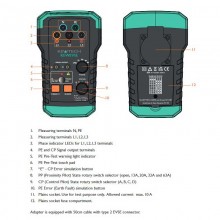
| EVSE Interface (EV charger function) tests | |
| 1. Proximity detection (PP) states: Read only |
No proximity. |
| Proximity detected, unlatched. | |
| Proximity detected, latched. | |
| 2. Control pilot (CP) Set and read states: |
State A – Disconnected. |
| State B – Connected. | |
| State C – Charging. | |
| State D – Charging without ventilation. | |
| State E – CP short to PE. | |
| Read-only state | State F – EVSE charger fault condition. |
| Maximum voltage | ± 14 V. |
| Frequency range | 940 Hz to 1040 Hz. |
| Duty cycle range | 8% to 97%. |
| Maximum charging current indication according to IEC 61851-1:2017, tables A.7 and A.8. | |
| Resistance of Earth Protective Earth Protective Conductor (RPE) | |
| Test current | 200 mA. |
| Resistance range | 0 to 10 Ω. |
| Resistance resolution | 0.01 Ω. |
| Resistance accuracy | ± 5% ± 2 digits. |
| RCD/GFCI Tests | |
| Trip time accuracy | ± 1% ± 1 ms. |
| Trip current accuracy | ± 3% (apply to all RCD/GFCI tests). |
| Personal Protection Tests, 230V Single Phase | |
| 1. RCD 30 mA ac TEST | |
| Test current | 31.5 mA AC (5% above nominal trip current). |
| Max. test time | 300 ms. |
| Polarity selection | 0° and 180° of an input sine wave. |
| 2. RCD 6mA dc Test | |
| Test current ramp | up at rate of 6 mA in 2.5 s, then held at 6 mA DC. |
| Ramp polarity | positive and negative ramp. |
| Max. test time | 12.5 s. |
| Polarity selection | 0° and 180° of an input sine wave. |
| Personal Protective Tests, 120V Single Phase/ 240V Two Phase | |
| 1. GFCI/CCID 5 mA ac test | |
| Test current | 6 mA AC. |
| Max. test time | 5.59 s. |
| Polarity selection | 0° and 180° of an input sine wave. |
| 2. GFCI/CCID 20 mA ac test | |
| Test current | 21 mA AC (5% above nominal trip current). |
| Max. test time | 5.59 s. |
| Polarity selection | 0° and 180° of an input sine wave. |
| Nuisance Tripping Tests, 230V Single Phase | |
| 1. RCD ac ramp test | |
| Test current | AC current ramp up to 30 mA in 2 mA steps. |
| Step time | 300 ms. |
| Max. test time | 4.5 s. |
| 2. RCD dc ramp test | |
| Test current ramp | up at rate of 6 mA in 2.5 s, then held at 3 mA DC. |
| Max. test time | 11.25 s. |
| Nuisance Tripping Tests, 120V Single Phase/ 240V Two-Phase | |
| 1. GFCI/CCID 5 mA AC test | |
| Test current | AC current ramp up to 6 mA in 0.5 mA steps. |
| Step time | 100 ms. |
| Max. test time | 1.2 s. |
| 2. GFCI/CCID 20 mA AC test | |
| Test current | AC current ramp up to 20 mA in 1 mA steps. |
| Step time | 100 ms. |
| Max. test time | 2 s. |
| Touch Voltage Test | |
| Options | 25 V or 50 V limit. |
| Test current typically 1/3 of RCD nominal test current | |
| Touch Contact Pad Test | Dangerous voltage indication at PE conductor. |
| Power Supply | |
| Battery | Four AA cells. |
| Connections | Type 2 male – main test connection. |
| 4 mm shrouded socket on base of handle – RPE test return connection. |
|
| Environment | |
| Operational temperature | 0 ºC to 40 ºC. |
| Storage temperature | -10 ºC to 70 ºC. |
| Operating humidity | 90% R.H. at +40 °C max. |
| Maximum altitude | 2000 m. |
| Dust and moisture ingress | IP40 to IEC60529 in use. |
| Safety | |
| Standards | IEC 61010-1:2010. |
| Safety category | CATII 300 V. |
| Languages | |
| User Interface | English, French, German and Spanish. |
| User guide | English, French, German and Spanish. |
| Dimensions and Weights | |
| Dimensions (L x H x W) | 24 x 18 x 8.6 cm. |
| Weight (without batteries) | 583 g. |
No customer reviews for the moment.
![]()
Includes: Continuity/earth bond lead Blow moulded caseEVA-T1 Type 2 to Type 1 connector adaptor.