![]()
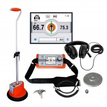
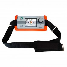
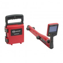
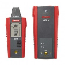
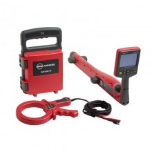
Includes: 1x AT-8000-RE Receiver, 1x AT-8000-TE Transmitter, 1x TL-8000-EUR Test Lead And Accessory Kit, 1x CC-8000 Hard Carrying Case, 1x User Manual & QSG, 3x Battery Chargers, 12x Rechargeable Batteries, 1x ADPTR-SCT-xx Socket adapter, 1x CT-400-EUR Signal Clamp, 1x HS-1 Magnetic Hanger.
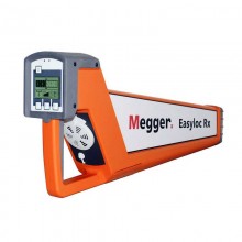
Tracing wires just got smarter, simpler and safer, even in the toughest industrial environments, the ONLY wire tracer rated for Category IV environments up to 600 volts.
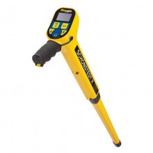
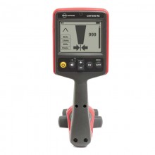
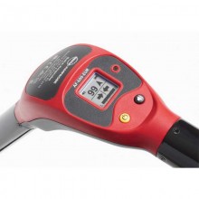
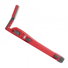
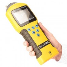
Save time, no blind searching - See hidden wires like never before with the AT-8000-RE Receiver’s patented Smart Sensor™, which finds and displays the location and orientation of energised wires in walls, floors and ceilings on the large colour TFT LCD screen. The Scan and Locate feature clearly identifies the single correct breaker or fuse, eliminating the confusion from multiple false positive readings common in older technology tracing tools. Embedded help screens make set-up easy and error free for novice users and experts alike.
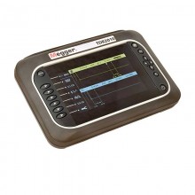
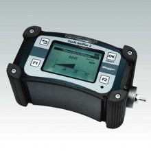
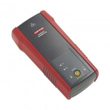
Featuring three power modes: "high", "low", and "loop" and two output frequencies (6 kHz and 33 kHz), the AT-8000-TE Transmitter incorporates the best technologies available for optimal wire tracing and breaker identification on both energised and de-energised circuits. The AT-8000-TE automatically sets the signal based on detected voltage and prompts the user to set the power level based on the application, delivering consistently accurate results.
FEATURES
Trace Energised and De-energised wires in walls, ceilings, floors and tight spaces.
Identify breakers and fuses.
Pinpoints shorts and opens.
Non-contact voltage mode and passive tracing.
High resolution 89 mm (3.5 in) TFT LCD color display.
Three power modes:
- "High" power mode for normal circuits.
- "Low" power mode for precision tracing in difficult areas.
- "Loop" power mode provides a boosted signal using the signal clamp.
Two automatically selected frequency modes for optimal tracing on energized and de-energized circuits.
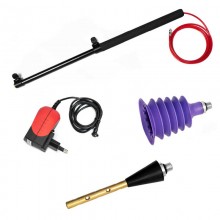
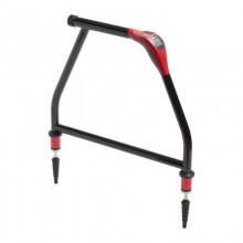
Optional CT-400-EUR Signal Clamp for inducing signal into wires without access to bare conductors (included in the AT-8030-EUR Kit only).
Embedded help screens for easy, error free set-up.
| Specifications | AT-8000-RE Receiver | AT-8000-TE Transmitter | CT-400-EUR Signal Clamp |
| Measurement Category | CAT IV 600 V | CAT IV 600 V | CAT IV 600 V, CAT III 1000 |
| Display size | 8.9 cm (3.5 in) | (LED signals) | - |
| Display Dimensions (W x H) | 70 x 52 mm (2.76 x 2.07 in) | - | - |
| Display Resolution | 320px x 240px | - | |
| Display type | Colour TFT LCD | - | |
| Colour Display | Yes | - | |
| Booting time | 30 sec | < 2 sec | |
| Backlight | Yes | - | |
| LED Indicator | Green Flashing: Signal Detection | Operating mode LEDs: red Battery status LEDs: green, yellow, red |
|
| Operating Temperature range | -20 °C to 50 °C (-4 °F to 122 °F) | -20 °C to 50 °C (-4 °F to 122 °F) | |
| Operating Humidity | 45%: -20 °C to <10 °C (-4 °F to <50 °F) | 45%: -20 °C to <10 °C (-4 °F to <50 °F) | - |
| 95%: 10 °C to <30 °C (50 °F to <86 °F) | 95%: 10 °C to <30 °C (50 °F to <86 °F) | 95%: 10 °C to <30 °C (50 °F to <86 °F) | |
| 75%: 30 °C to <40 °C (86 °F to <104 °F) | 75%: 30 °C to <40 °C (86 °F to <104 °F) | 75%: 30 °C to <40 °C (86 °F to <104 °F) | |
| 45%: 40 °C to 50 °C (104 °F to 122 °F) | 45%: 40 °C to 50 °C (104 °F to 122 °F) | 45%: 40 °C to <50 °C (104 °F to <122 °F) | |
| Storage temperature and humidity | -20 °C to 70 °C (-4 °F to 158 °F), ≤ 95% RH | -20 °C to 70 °C (-4 °F to 158 °F), ≤ 95% RH | -20 °C to 60 °C (-4 °F to 140 °F), ≤ 95% RH |
| Operating altitude | 0 to 2000 m (0 to 6561 ft) | 0 to 2000 m (0 to 6561 ft) | 0 to 2000 m (0 to 6561 ft) |
| Transient protection | - | 8.00 kV (1.2/50μS surge) | - |
| Pollution degree | 2 | 2 | 2 |
| IP Rating | IP 52 | IP 40 | IP 40 |
| Drop test | 1 m (3.28 ft) | 1 m (3.28 ft) | 1 m (3.28 ft) |
| Power Supply | 4 x AA (alkaline or NiMH rechargeable) | 8 x AA (alkaline or NiMH rechargeable) | - |
| Power consumption | 4xAA battery: 2W | Hi/Lo mode: 70 mA Loop mode with Clamp: 90 mA Consumption without signal transmission: 10 mA |
- |
| Battery life | Approx. 9 h | Hi/Lo mode: approx. 25 h Loop mode: approx. 18 h |
- |
| Low battery indication | Yes | Yes | - |
| Fuse | - | 1.6 A, 700 V, fast-acting, Ø 6x32mm |
- |
| Maximum conductor size | - | - | 32 mm (1.26 in) |
| Response time | Smart mode: 750 ms | Line voltage monitoring: 1 sec | Instantaneous |
| Tip Sensor Energised: 300 ms | |||
| Tip Sensor De-Energised: 750 ms | Battery voltage monitoring: 5 sec | ||
| NCV: 500 ms, Battery monitoring: 5 s | |||
| Voltage Warning Indicator | - | > 30 V AC/DC | - |
| Non-Contact Voltage (NCV) | 90-600 V AC | - | - |
| Signal indications | Audible beep, bargraph display, numeric display | LEDs and audible beep | - |
| Operating Frequency | Energised: 6.25 kHz | Energised: 6.25 kHz | Loop Mode: 6.25 kHz |
| De-Energised: 32.768 kHz | De-Energised: 32.768 kHz | High / Low Mode: 32.768 kHz | |
| Acoustic Indication | Piezo Buzzer | Audible beep | - |
| Range Detection (Open air) | SmartSensor™: Pinpointing: Around 5 cm (2 in) radius (+ - 2%) Direction indication: Up to 1.52 m (5 ft) (+ - 2% |
- | - |
| Tip sensor (Energised): Pinpointing: Around 5 cm (2 in) (+ - 1%) Detection: Up to 6.7 m (22 ft) (+ - 1%) |
|||
| Tip sensor (De-energised): Detection: Up to 4.3 m (14 ft) (+ - 5%) |
|||
| NCV detection (40 to 400 Hz): Pinpointing: Around 5 cm (2 in) radius (+ - 5%) Detection: Up to 1.2 m (4 ft) (+ - 5%) |
|||
| Current Output of signal (typical) | - | Energised circuit: HI mode: 60 mA RMS LO mode: 30 mA RMS |
- |
| De-energised circuit: HI mode: 130 mA RMS LO mode: 40 mA RMS Loop mode: 160 mA RMS |
|||
| Signal voltage output (nominal) | - | De-energised circuit: LOW: 29 V RMS, 120 Vp-p HIGH: 33V RMS, 140 Vp-p With CT-400-EUR: loop mode: 31 V RMS, 120 Vp-p |
- |
| Dimensions (L x W x H) | Approx. 278 x 113 x 65 mm (10.92 x 4.43 x 2.55 in) |
Approx. 183 x 93 x 50 mm (7.2 x 3.66 x 1.97 in) |
Approx. 150 x 70 x 30 mm (5.9 x 2.75 x 1.18 in) |
| Weight | 0.544 kg (1.20 lb) | Approx. 0.57 kg (1.25 lb) | Approx. 0.114 kg (0.25 lb) |
No customer reviews for the moment.
| COMPONENT |
DESCRIPTION | PART No. | ||
| Test Lead And Accessory Kit | Kit includes: 2 x 1 m test leads (red, black) 1 x 7 m test lead (green) 2 x alligator clips (red, black) 2 x test probes (red, black). |
5117915 | ||
| Test lead | 25 Metre. Suitable for AT-8000-EUR series. | 5215545 | ||
| Case | Hard Carry Case. | 5088854 | ||
![]()
Includes: 1x AT-8000-RE Receiver, 1x AT-8000-TE Transmitter, 1x TL-8000-EUR Test Lead And Accessory Kit, 1x CC-8000 Hard Carrying Case, 1x User Manual & QSG, 3x Battery Chargers, 12x Rechargeable Batteries, 1x ADPTR-SCT-xx Socket adapter, 1x CT-400-EUR Signal Clamp, 1x HS-1 Magnetic Hanger.